
Technology
High-Speed Lapping
Only 10X Faster High-Speed Abrasive Wafer Polishing System

Keltech has the only high-speed abrasive polishing system in the world.
Sapphire wafers are polished 10X to 50X faster than by conventional liquid abrasive slurry polishing systems.
From 10 to 50 slurry machines can be replaced by a single island disc machine.
Abrasive islands prevent water-spray cooled wafers from hydroplaning at high abrading speeds. Vitrified diamond abrasive agglomerates in the islands provide high sapphire cut rates and long abrade life of the discs.
Multiple abrading tests of sapphire wafers have verified the high speed performance of the island discs.
The Keltech vitrified diamond agglomerate island discs are a new form of abrasive media.

Tests Verify High Cut Rates, Long Disc Abrade Life
Many high-speed sapphire abrading tests of Keltech vitrified diamond agglomerate island 12” discs on the lapper machine using 40-50 micron diamond particles have shown very high cut rates.
Hundreds of abrading tests using 6” island discs to abrade 2” sapphire wafers with 30 micron diamonds have verified both high wafer cut rates and long disc abrade life. See the DATA section for more info.
Abrasive Discs, Lapper Machine System

Vitrified diamond agglomerate island discs with 12” and 18” diameters are quickly mounted with vacuum on a lapper machine platen that rotates up to 3,000 rpm.
Wafers are also attached with vacuum to a 6” wafer head that applies controlled abrading pressure when the rotating wafers contact the rotating abrasive island disc.
Water spray is applied to the rotating island disc to cool the wafers while they are abraded.
Abrasive Islands Prevent Hydroplaning

High speed abrasive lapping and polishing requires the use of abrasive islands to prevent hydroplaning of workpieces.
Hydroplaning can occur at high speeds where a thin water film lifts the wafers, preventing contact with the abrasive.
One analogy is hydroplaning that lifts a boat up in the water at high speeds.
Another analogy is where bald car tires hydroplane at high speeds on a wet road but where tire tread lugs (disc islands) prevent hydroplaning.

Porous Abrasive Islands Provide Controlled Wear-Down

The abrasive agglomerate filled islands must be porous to provide a controlled rate of eroding due to wafer wear.
This eroding action allows wafer high and consistent cut rates to occur as the islands slowly wear down.
Solvent-based phenolic adhesives are used to strongly bond the abrasive agglomerates together in the island structures. As the solvent evaporates, voids are formed, making the islands porous.
Vitrified Diamond Agglomerates Provide High Cut Rates


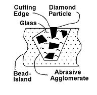
Vitrified diamond abrasive particles are encapsulated in rigid glass agglomerates which strongly supports them while abrading wafers.
To produce the agglomerates, diamond particles are mixed with glass powder and heated to 700 degrees C in a furnace to fuse them together. The diamonds are protected from oxygen in the furnace as they carburized and evaporate above 500 degrees C. After cooling the fused mix is fractured into small agglomerates.
As each diamond particle progressively wears down, its leading cutting edge is continually re-sharpened by abrading action. Here, all the expensive diamond particles are fully utilized before they are replaced by new particles in the island agglomerates.
These vitrified agglomerates provide both high wafer cut rates and long disc abrade lives.
Flat-surfaced agglomerates are shown on the surface of worn islands.
Porous Layer Between Islands Carries Coolant Water
A porous layer of adhesive joint-bonded foam-glass beads between islands carries water to the wafers during abrading operations. A very thin film of water on the wafer allows the abrasive particles to contact and abrade the wafer surface.
The film of water on the wafer surface removes heat generated by abrading friction.
Also, the porous layer between the islands provides a very distinctive appearance to these high speed island abrading discs.


Annular Bands of Islands Required on Discs
Annular bands of abrasive islands are required.
Wafers overhang both the inner and outer annular radii to provide uniform wear-down of both the wafers and the abrasive islands.
Annular bands of abrasive are used both for CMP liquid abrasive slurry polishing and for the abrasive island discs.
Abrasive discs have a wide range of diameters (up to 60” or more) with different radial widths of the annular bands of islands.

Diamonds Required to Abrade Sapphire, SiC, GaN
Sapphire, SiC and GaN are almost as hard as diamond.
However, diamond is harder and when used at high speeds, cuts these materials readily.
Fully Utilized Individual Diamond Particles
Only some of the abrasive particles in an abrasive slurry are fully utilized. They are continually supplied in a liquid stream during the abrading operation.
Spent slurry, containing old and new particles and abrading debris, is continually washed off the abrading surface of the platen.
By comparison, with the island discs, each individual fixed-abrasive diamond particle encapsulated by glass in the agglomerates is fully utilized as it slowly wears down during abrading.
Wide Range of Disc Sizes, Abrasive Materials
Island discs are available in sizes ranging from 6” to 60”, or more.
A wide variety of abrasive particle materials including diamond, CBN, SiC, and aluminum oxide can be encapsulated by glass in the vitrified agglomerates.
Daimond abrasive particle sizes range from 3 microns to 50 micron.
Percent Diamond Particles In Agglomerates
The cut rates and disc abrade life can be affected by many variables.
These include: the percent and size of diamond particles in the vitrified abrasive agglomerates, the quantity of agglomerates, the porosity of the islands, and the abrade speeds and the abrade pressures.
Island Discs Used Before CMP Polishing
Rough-surfaced sliced sapphire, SiC and GaN wafers can be quickly flattened and polished with island discs in preparation for CMP polishing.
Then, the loose-abrasive slurry particles in the CMP system can be used to finish-polish the wafers.
Use CMP Chemicals With Island Discs
The chemical additives used to “soften” the surfaces of wafers for faster CMP abrading can also be used with the abrasive island discs.
These chemicals can be simply added to the coolant water that is sprayed on the island disc when abrading wafers.
3M Fixed-Abrasive Diamond Trizact Tile Abrasive Discs
DISCS ATTACHED TO CONVENTIONAL LAPPER MACHINES
3M’s Diamond Tile fixed-abrasive discs are actively used for polishing wafers and workpieces without a slurry mess. The discs can be used on conventional slurry abrading machines by attaching them with PSA (adhesive) to an annular slurry platen. Changing the abrasive sizes is difficult with the PSA bonded discs.
Some of the Trizact discs are also attached to platens with Hook & Loop materials that do not provide stiff and stable support of the discs.
DISCS CUT FROM CONTUINOUS WEBS
The Trizact discs are produced from continuous webs where circular disc shapes are cut out from the webs. Excess diamond abrasive tile web material (weed) between the circular discs is discarded. Also, to provide discs with annular bands of abrasive, the disc center-holes are also cut out of the discs and discarded.
PRE-GRIND DISCS BEFORE START ABRADING
Before the discs can be used for abrading, about 10% of the thickness of the abrasive tiles top surfaces must be ground off each disc. Here, it is necessary to remove a disc-surface polymer coating to expose the diamond particles for abrading. This initial pre-conditioning disc grinding process is an extra time-consuming process step that must be completed before workpiece abrading starts.
SMALL AND THIN ABRASIVE TILES USED ONLY AT SLOW SPEEDS
The water-cooled small tiles are separated with narrow grooves where the square tile structures (islands) are solid, not
porous. Even medium abrading speeds cause hydroplaning of workpieces.
3M Trizact Discs vs Keltech Island Discs

ISLAND DISCS USED ON EXISTING SLURRY LAPPER MACHINES
Island discs having “soft” diamond abrasive agglomerates can be used to polish wafers at very low speeds on the many existing slow-speed abrasive slurry lapping machines. The fixed-abrasive island discs can be attached to the slow speed platens with PSA applied to the disc backing substrate.
The “soft” agglomerates also can erode easily at very low abrade forces. Soft agglomerates can be produced by adding foam glass beads to the abrasive particle and synthetic glass powder mixture before vitrification in a furnace. Also, soft agglomerates can be produced by mixing a solvent-based adhesive with diamond particles and molding very small “Cubes” that erode easily.
VACCUM ATTACH DISCS ON SLURRY LAPPER MACHINES
Island discs can be easily and quickly attached (and interchanged) with vacuum on existing slurry lapper machines. This allows discs with smaller abrasive particles to be sequentially used for polishing wafers. A circular stainless steel vacuum plate is attached with an adhesive to the lapping machine platen. The stainless plate has a pattern of shallow vacuum grooves on its top surface. Also, a circular soft foam rubber O-ring recessed in a circular groove at its periphery is used to provide a vacuum seal for the island disc.
A vacuum port hole at the stainless plate center is coupled through a platen vertical hollow rotary drive shaft to a rotary union attached at the lower end of the drive shaft. Vacuum supplied to the stationary rotary union is coupled with the distributed shallow grooves on the plate surface. The vacuum strongly bonds the flexible island abrasive disc to the platen flat surface.
To remove the stainless plate from the platen, water is applied to the rotary union and injected in the layer between the platen and the island disc. A pattern of shallow surface grooves on the bottom surface of the stainless plate can help distribute the water over the whole island disc backing surface to separate the disc from the platen.
Additives such as soap can be added to the water or solvents such as acetone can be injected under the adhesive bonded island discs to separate them from the platen.
HIGH FRICTION PLATEN SURFACE FOR VACUUM DISC
Applying a fine grit abrasive coating on a platen surface provides increased friction for vacuum-attached abrasive discs. Large disc clamping forces from the vacuum drives the disc backing against the protruding sharp-pointed abrasive grits which “bite” into it. Very shallow penetration of the abrasive particles into the disc backing provides a large increase of the sliding friction of the disc relative to the platen surface.
Increasing the friction allows very high abrading shear forces to be applied to the abrasive discs without separating them from the platen when abrading a wafer or workpiece.
Abrasive particles can be mixed with a high-solvent adhesive and spin-coated on the platen surface. After solvent evaporation, a mono layer of particles protrude above the platen surface. If desired, the high-friction abrasive particle coating can be removed (or replaced) from the platen by using a solvent.
Use of small 320 grit abrasive particles allows a strong vacuum seal to exist over the full surface of the disc backing. The uniform thickness of the thin mono layer of particles on the platen also assures that the top abrading surface of the island abrasive disc remains in a precisely flat and rigid abrading plane.
Applying a medium vacuum produces 10 psi clamping across the full surface of the disc. This vacuum produces a total clamping force of about 1,000 lbs on a 12” diameter disc.
Abrasive discs can be repeatedly removed and replaced with the abrasive grit coated platens because the very small grit particles only temporarily indent the surface of the polymer disc backing.
VITRIFIED DIAMOND AGGLOMERATE PRODUCTION
The vitrified diamond agglomerates are produced by mixing diamond abrasive powder with a synthetic glass powder and water to form a thick paste. The abrasive paste mixture is then spread out to form thin slabs on 0.001” thick pre-oxidized stainless-steel strips placed on a stiff stainless plate. The stainless strips are pre-oxidized at about 600 C to form a thin brown coating on them. Another 0.001” thick pre-oxidized stainless steel thick strip is placed on the abrasive paste mixture slab top surface. A heavy steel block is placed on top and squeezed flat to contact 0.045 diameter steel gap wires that are placed on both sides of the slabs. The squashed slabs typically have a uniform 0.045” thickness and are about 2” wide and 3” long.
The abrasive mix /stainless sandwich with the steel block weight is then placed in a furnace and heated to about 700 C to melt the glass powder that then encapsulates the diamond particles. The synthetic glass powder typically melts at a temperature as low as 500 C. The stainless strips seal the top surface of the abrasive mixture and prevent contact of the hot 700 C furnace air with the encapsulated diamond particles present at the surface of the mixture. Diamonds will degrade thermally when directly exposed to oxygen above 500 C but the top stainless strip shield prevents this contact.
When the glass has melted and encapsulated the diamond particles, the furnace is cooled to about 350 C and the vitrified stainless steel abrasive slab sandwiches are quenched in water. Here, thermal stresses due the differential shrinkages of the stainless and the slabs separates the slabs from the stainless. The oxide coating on the stainless prevents bonding of the glass in the vitrified slabs to the stainless strips.
After the thin and rigid diamond abrasive slabs are dried, they are placed in small plastic bags that are placed in flat-surfaced contact with a metal plate. The slabs are then rough-split into small vitrified agglomerate pieces by using sharp pointed tools that penetrate the top surface of the plastic bags and are forced partially into the slab surfaces. The bag restrains the large-sized agglomerates as a single layer as the rigid slabs are split.
The bag containing the single layer of large-sized loose agglomerates is then end-taped to the horizontal table of a motor driven X-Y slide. Then, a “gang” of multiple sharp-pointed carbide tipped scribe points are bonded together and attached to a vertical slide. The vertical slide is driven up and down by a gear motor where the scribe points penetrate the plastic bag top surface and partially into the slab thickness but do not contact the slide horizontal table surface. The relative speed of the vertical gear motor and the horizontal table slide motor are controlled to provide uniform sized agglomerates as the multiple scribe points split the loose large-sized agglomerates into the desired smaller sized agglomerates. After a “path” of agglomerates are split, the X-Y table is advanced sideways and the gang of multiple scribes spilt another parallel “path” of agglomerates.
Split agglomerates are then removed from the bag having the bag top surface shredded by the scribe points. The agglomerate slabs typically are 0.045” thick and are spilt into cross-sectional pieces that rage in size from 0.016” to 0.045” . These agglomerates are easily molded into raised islands, attached to a disc backing, that are 0.061” high and have a diameter of 0.186”.
Because the slabs are split into agglomerate pieces there is very little debris formed by the splitting action. Undersized agglomerates containing diamond particles can be collected and recycled in another batch of the vitrified abrasive slabs.
If the rigid vitrified agglomerate slabs are crushed by conventional techniques, they tend to break partially into agglomerate powder that is too small to perform well for abrading wafers. Splitting the vitrified slabs with the sharp-pointed tools avoids creating the undersized agglomerate debris.
“SOFT” VITRIFIED DIAMOND AGGLOMERATE PRODUCTION
“Soft” vitrified diamond agglomerates can be produced that easily erode at low abrading speeds and low abrading pressures. Here, small foam glass beads are mixed with diamond powder, synthetic glass powder and water to make a paste that is formed into thin slabs. The slabs are heated to 700 C in a furnace where both the beads and diamonds are encapsulated by the melted glass. The synthetic glass melts below 700 C but the high-melt-temperature foam glass beads remain intact. Because the foam glass beads are soft and fragile, the resultant split abrasive agglomerates are easily eroded at low abrade forces. Island discs with the “soft” abrasive agglomerates can then be used on the many existing slow-speed slurry lapping machines.
“CUBE” DIAMOND AGGLOMERATE PRODUCTION


Cube-shaped diamond abrasive agglomerates can be mold-formed from a mixture of diamond powder and an adhesive. A thin and flexible RTV silicon rubber mold with an array of small receptacle pocket holes can be level filled with a mixture of diamond powder and an adhesive which is solidified. After solidification, the small molded agglomerates are easily separated from the flexible mold as the cube agglomerate adhesive does not bond to the RTV silicon rubber. The agglomerate cubes typically have 0.040” X 0.040” X 0.040” sizes.
Using an epoxy adhesive, the agglomerate cubes can be almost as rigid as vitrified agglomerates. Foam glass beads can also be mixed with the diamond abrasive particles and the epoxy adhesive to provide “soft” cubes that erode easily for low-force wafer abrading.
The RTV mold can be easily made by cutting an X-Y pattern of posts in a polymer or metal plate and placing a thin edge dam around the X-Y plate. Then liquid RTV silicon rubber is poured into the post plate matrix of holes level with the edge dams to fill the gaps between the posts with a thin and uniform thickness above the posts. After curing the RTV rubber, the thin and flexible RTV agglomerate cube sheet is peeled of the polymer mold.
Solent-based adhesives can also be used to mold-form abrasive cubes that are porous. When the abrasive mixture in the RTV mold holes are heated, solvent evaporates from the adhesive solvent and the adhesive shrinks and forms voids between the diamond abrasive particles. The resultant porous cubes have high wafer cut rates and high erodibility when used at low abrading forces using existing slurry lapping machines.
RUBBER ISLAND-MOLD FONT SHEET

A rubber font sheet having a pattern of through-holes is used to mold-form the island structures with a mixture of abrasive agglomerates and a solvent-based adhesive. An array of holes in the rubber sheet are used to form an annular band of islands that are bonded to a disc backing substrate. The island structure heights are equal to the thickness of the rubber font sheet and the diameters of the islands are equal to the diameters of the font sheet holes.
Either silicone rubber or nitrile rubber sheets can be used to make the island hole font sheet. Both rubbers are flexible and resist bonding of adhesives used in the island abrasive mixtures. To construct the abrasive islands, a solvent based adhesive, such as phenolic, is coated on the disc substrate abrasive-roughened surface and allowed to partially dry, which makes the phenolic tacky. The rubber hole sheet is placed in flat-surfaced contact with the tacky adhesive to lightly-bond the rubber to the disc substrate and to seal the bottoms of each of the island holes. A 0.031” thick epoxy fiberglass substrate provides limited flexibility, excellent adhesive bonding and good thermal stability for 250 F temperature curing of the phenolic adhesive without distortion.
A mixture of diamond abrasive agglomerates and the solvent-based phenolic is level-filled in all of the rubber font sheet holes with a squeegee. Here, the “wet” phenolic in the island abrasive mixture contacts the phenolic coating on the disc substrate that is exposed in each of the rubber holes. Upon curing of the phenolic adhesive, the islands are strongly bonded to the surface of the disc substrate. After the phenolic adhesive is cured, the flexible rubber font sheet can be easily peeled off both the disc backing substrate surface and from the mold-formed island structures bonded to the substrate.
Islands having a diameter of 0.186” and a height of 0.061” are formed when 0.186” diameter holes are punch-cut in 0.061” thick rubber sheets. The island through-holes can also be laser cut or water jet cut in the rubber sheets.
SOLVENT BASED ADHESIVE ISLAND CONSTRUCTION


Islands that are mold-formed using solvent-based adhesives require special procedures due to evaporation of the adhesive solvent. When a mixture of agglomerates, foam glass beads and the solvent adhesive is level-filled in the rubber mold sheet holes, the mixture is then heated by conduction from the island bottom. Heating the mixture evaporate the solvent in the adhesive which creates solvent-fume gas bubbles that expand within the island structures. As the gas bubbles expand within the islands, they tend to push the island abrasive mixtures up and out of the rubber island mold holes.
To restrain the abrasive mixtures within the rubber holes, a thin RTV silicone rubber flexible sheet having a X-Y pattern of small posts is placed on top of the island surfaces and the rubber mold sheet surface. The thin and flexible rubber posts conform to the island top surfaces. Then a layer of flexible foam rubber is placed on the RTV post sheet and a flat plate and a weight are placed on the foam rubber. Upon heating, the evaporated solvent fume bubbles push upward in the islands and break at the island surfaces while the RTV rubber posts retain the island mixture within the islands. The solvent gas bubbles burst at the island surfaces where the gas is routed outward from the islands by the open passageways between the posts on the RTV post sheet. Heating is continued until all of the solvent is exhausted and the adhesive is fully solidified.
Upon full curing of the island adhesive, the island structures are uniformly porous from top to bottom and the islands have flat exposed top surfaces.
ADD SOLVENT TO PHENOLIC ADHESIVE
Commercially available phenolic adhesive having approximately 22% alcohol solvent is typically quite thick with high viscosity. When mixed with vitrified diamond agglomerates, the thick mixture is difficult to level-fill the island holes in the rubber hole font sheets. However, the viscosity of the mixture can be significantly lowered by adding denatured alcohol to the phenolic. Increasing the total alcohol in the phenolic adhesive to about 50% results in a very “liquid” abrasive agglomerate mixture that is easily used to level fill multiple island holes in the rubber font sheet with a squeegee.
RTV RUBBER “POST” SHEET FOR ISLANDS
The RTV rubber “post” sheet can be easily made by using a thin metal plate that is etched with a X-Y pattern of rectangular holes. This hole-plate can be attached to a flat plate and thin edge dams can be attached on the top surface of the hole-plate around the outer periphery of the hole-plate etched holes. The edge dam top surfaces extend a small distance above the hole-plate surface. Then liquid RTV silicon rubber is poured into the hole-plate matrix of holes and also level with the top of the edge dams. The RTV fills the holes and also forms a thin and uniform thickness layer above the holes to create a rubber sheet having integral posts that protrude above the sheet surface.
The “post” holes etched into the metal font hole-plate can form an annular pattern that “surrounds” the annular band of islands that are bonded to a disc backing substrate. The post holes extend both radially inward and outward from the annular band of islands to route the solvent gas fumes radially away from the islands as the solvent is evaporated. Large post screens are made for large island discs.
After curing the RTV rubber, the thin and flexible RTV agglomerate “post” sheet is easily peeled off the etched metal hole-plate.
Square posts in a X-Y array pattern provide gas exhaust open channels between the posts. Typical RTV silicon rubber posts have cross-sectional sizes of 0.035” X 0.035” with gaps of 0.025” between posts and with post heights of 0.025”. The total thickness of the flexible post sheet is about 0.050”, including the heights of the protruding posts.
Adhesives in the abrasive agglomerate island mixtures will not bond to the RTV silicone rubber post sheets.
Adhesives in the abrasive agglomerate island mixtures will not bond to the RTV silicone rubber post sheets.
SIMPLE & INEXPENSIVE “BATCH” ISLAND DISC PRODUCTION


ISLAND DISC BATCH PRODUCTION
Small Batches of island discs can be produced at low costs with a simple benchtop operation. Expensive web-line production facilities are not required to produce these flexible discs having annular bands of islands. During production, rubber sheets with a pattern of island holes are joined with flexible and strong backing sheets. The rubber holes are filled with a liquid mixture of a solvent-based phenolic adhesive, diamond abrasive agglomerates and foam glass bead fillers. When the solvent is evaporated from the adhesive in an oven, it shrinks and forms a porous island. Oven curing the adhesive provides a strong bond of the abrasive island structures to the disc backing. The rubber mold sheet is then peeled off the backing and a porous mixture of foam glass beads and epoxy is placed between the islands and bonded to the disc backing. After curing the bead filler, the top surface of the islands are ground flat into a mutual plane where the diamond particles are exposed, ready for abrading workpieces and wafers. Further, the disc backing has a continuous flat surface which allows it to be quickly attached with vacuum to a platen. A wide range of disc sizes and geometries can be quickly produced at low cost.
EXPENSIVE DIAMONDS UTILIZED
All of the expensive diamonds used to make the island discs are fully utilized when they are encapsulated in the annular band of islands bonded to the disc backing. By comparison, a significant amount of the diamond material is lost as scrap when 3M Trizact annular discs are cut out of a continuous web. Further, when the center of a Trizact annular disc is cut out, the disc can no longer be attached with vacuum to a platen. Instead, Trizact discs are bonded with an adhesive to platens. Batch production of individual island discs is similar to producing batches of annular discs that are individually cut out of a continuous abrasive web material.
PRODUCTION of MANY DISCS
Simple automated disc processing equipment can be added to the production line for large volumes of the island discs.
DISC PRODUCTION STEPS ARE DESCRIBED BELOW
Sequential numbered steps for the production of the abrasive island discs are descried in the following.
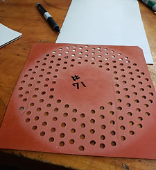
#1 PRE-CUT RUBBER MOLD SHEETS


PRE-CUT COMPOSITE RUBBER ISLAND MOLD SHEETS
Small Batches of island discs are made using multiple composite rubber island mold sheets having a square outer shape. Each pre-cut rubber island mold sheet has three free-standing concentric parts that fit each other.
Rubber Sheet Outer PART #1.
The outer rubber part has a square rubber outer shape with a circular inner shape having a diameter equal to the island abrasive disc diameter.
Rubber Sheet Middle PART #2.
The middle rubber part has an annular shape with a circular outer shape with a diameter equal to the island abrasive disc diameter. The rubber annular shape has an annular pattern of small diameter through holes used to mold the island structures. The height of the islands is equal to the thickness of the rubber sheet.
Rubber Sheet Inner PART #3.
The inner rubber part is a circular discs. The inner rubber disc provides a flat open circular are at the abrasive disc center that is free of the annular band of islands and porous beads.
Water Jet Cut Multiple Rubber Island Sheets
Stacks of rubber sheets can be stacked and cut with a water jet. Each set of three rubber sheet parts can be reused repeatably to produce more island discs.
#2 PRE-CUT COMPOSITE FIBERGLASS BACKING SHEETS

PRE-CUT COMPOSITE ISLAND DISC BACKING SHEETS
Disc Backing Sheet: PART #1.
The composite fiberglass disc backing sheet has a Part #1 square fiberglass outer shape with an integral Part #2 circular inner shape.
Integral Circular Disc Backing Sheet: PART #2.
The disc backing sheet integral Part #2 inner circular shape has a diameter equal to the outer diameter of a completed island disc. The inner circular part is joined with the outer square part to form an integral composite sheet. The two parts are structurally attached to each other with four small integral radial tabs (shown in black). Also, a narrow annular segmented circular groove substantially separates the two parts.
Water Jet Cut Multiple Composite Backing Sheets
Stacks of square fiberglass sheets can be stacked up and simultaneously cut with a water jet to form multiple composite island disc backing sheets. Four annular segments of narrow grooves are cut in the fiberglass sheets which leave the four small tabs connecting the inner and outer parts of the backing. The tabs allow the whole composite backing sheet to be handled during production of the discs.
The composite backing sheets can be made in bulk quantities that are stored for future production of the abrasive island discs.
#3 NON-STICK COATING ON RUBBER MOLD SHEET SURFACES
A non-stick coating is applied to the top surface of the three-part composite rubber sheets and to the island hole sidewalls in the rubber sheet. This coating prevents the phenolic adhesive in the island abrasive mixture from bonding to the rubber sheet after the phenolic is cured.
Paraffin wax is dissolved in acetone and sprayed on the top (only) rubber surface and the hole sidewalls. Upon drying, a thin film of non-stick wax covers the rubber and prevents bonding of the phenolic adhesive to the rubber.
#4 BOND RUBBER MOLD SHEETS TO BACKING SHEET

During construction of an abrasive island disc, a coating of liquid phenolic adhesive is applied to the surface of the two-part composite fiberglass backing sheet. Solvent is evaporated from the adhesive to provide a tacky surface. Then, the bottom surfaces of the three-part composite square rubber island mold sheets are aligned with the two-part composite square fiberglass backing sheets and temporarily bonded together with the tacky phenolic adhesive.
The adhesive bonds the rubber to the fiberglass sheet to prevent hole-bottom leakage of the liquid phenolic abrasive agglomerate mix that is placed in the island holes. Also, the tacky phenolic coating, that is exposed at the bottom of the holes, provides strong bonding of the island phenolic abrasive mix to the fiberglass backing.
#5 MIXTURE OF DIAMOND AGGLOMERATES, ADHESIVE
Vitrified diamond agglomerates, foam glass bead fillers and phenolic adhesive are mixed to form a “liquid” mixture. A measured volume of the mixture is made that equals the total volume of all the island holes in the rubber mold sheet. Alcohol solvent is added to the phenolic adhesive to provide a liquid abrasive mixture that flows easily into the rubber island holes.
#6 FILL ISLAND HOLES WITH ABRASIVE MIXTURE

The liquid abrasive mixture is deposited on the rubber surface and spread over the island holes with a squeegee. All of the island holes are filled level with the rubber surface.

#7 EVAPORATE SOLVENT FROM PHENOLIC ADHESIVE


A thin and flexible silicone rubber “Post” sheet is placed on top of all the abrasive mixture filled islands. This is done to restrain the abrasive mixture in the holes as the rubber and backing sheets are heated in an oven to evaporate the solvent. As the phenolic adhesive is heated at low temperatures in an oven, the solvent vaporizes and tends to push the mixture up and out of the holes. The “Post” sheet restrains the mixture in the holes.
However, the X-Y pattern of grooves between the bosses on the surface of the “Post” sheet allows the solvent vapor to exit each island hole. Phenolic from the abrasive mixture does not bond to the silicone rubber sheet.
When the phenolic solvent is evaporated, localized shrinkage of the adhesive creates porous islands.
Multiple island backing/rubber sandwich sheets are stacked in the oven to evaporate the island abrasive mixture phenolic solvent of each sheet at the same time.
#8 OVEN CURE THE ISLAND’S PHENOLIC MIXTURE

After the solvent is evaporated from the abrasive phenolic adhesive, the oven temperature is increased to fully cure the phenolic and strongly bond the porous islands to the disc backing. Also, all of the vitrified diamond agglomerates are strongly bonded within the islands to resist abrading forces.
The stacked backing/rubber sandwich sheets are heated together in the oven to solidify the island abrasive mixture phenolic adhesive of each sheet at the same time.
#9 REMOVE THE RUBBER ANNULAR ISLAND SHEET

After the rubber and backing sheet sandwich is removed from the oven and cooled, the rubber annular island sheet is peeled off the fiberglass backing sheet. This exposes all of the annular band of island structures bonded to the backing sheet.
The rubber sheet having the square outer shape and the rubber circular inner disc are left bonded to the fiberglass backing sheet.
A dark colored rubber square sheet is shown to provide contrast of the components.
#10 APPLY POROUS BEAD FILLER BETWEEN ISLANDS

A controlled volume of 0.50 to 1.0 mm foam glass beads is mixed with a measured volume of slow-cure epoxy to only wet the surfaces of the beads but leaves voids between them. The epoxy/bead mix is spread over the disc islands that are exposed in the open annular space between the outer square rubber inside circle edge and the inner rubber disc outside circle edge.
The bead mix is then covered with a sheet of non-stick parchment paper, and a roller is used to squash the mix into contact with the disc backing.
After the epoxy is cured, the porous epoxy/bead mix is bonded to the disc backing and to the sidewalls of the island structures. The top surface of the epoxy/bead mix is level with the top surfaces of the islands.
Also, the porous bead mix has defined and smooth inner and outer annular borders.
#11 PEEL THE INNER RUBBER DISC OFF THE BACKING

The rubber inner disc is peeled of the disc backing to provide a flat circular area at the center of the island disc.
#12 PEEL THE OUTER SQUARE RUBBER SHEET OFF THE BACKING

The rubber outer square border sheet is peeled of the disc backing to expose the outer portion of the fiberglass backing sheet.
The fiberglass outer backing portion has an outer square shape and four narrow annular grooves (shown in black) that surround the island disc diameter. Four evenly spaced small integral tabs (shown in white) around the circumference of the island disc connect the backing outer square border with the backing inner disc center.
#13 CUT THE OUTER SQUARE BACKING OFF THE BACKING DISC

After the island disc is constructed, the four tabs are cut off the island disc backing to provide a disc with a smooth-surfaced backing disc edge.
#14 GRIND A RECESSED CIRCLE AT THE DISC BACKING CENTER
After the four tabs are cut off the disc backing, the center circular area of the backing disc is ground flat and smooth. This center area is recessed about 0.005” into the surface of the fiberglass backing which is below the bases of the abrasive islands that are bonded to the backing disc.
During abrading use of the disc, the recessed center area of the disc allows the abrasive islands to be completely worn off the backing without disturbing the ink-marked disc abrasive identification located at the disc center.
#15 GRIND THE TOP SURFACE OF THE ISLANDS AND POROUS BEADS
When the disc backing center circular area has been ground flat, the top surface of the islands and the surrounding porous beads are ground flat into a common plane that is parallel to the disc backing bottom surface. This parallelism allows the island disc to be operated at high speeds with smooth abrading contact of all the disc islands with a workpiece.
Also, the island surface grinding exposes the diamond particles before the disc is first used for abrading.
By comparison, a disc preconditioning surface grinding action is required before 3M Trizact discs can be used to abrade a workpiece. For Trizact discs, the user must first grind away a polymer film to expose the diamonds located at the disc surface for abrading action.
#16 ADD INK-MARKED ABRASIVE IDENTIFICATION TO DISC

The identity of the disc abrasive material and the abrasive particle size are screen printed in the smooth recessed area at the disc center. The recessed area protects the disc identity information from abrading even as the island structures are completely worn off the disc backing.
#17 BATCH ISLAND-DISC PRODUCTION SUMMARY
PRODUCTION PARAMETER
-
Simple Benchtop Disc Production
-
No Expensive Web-Line Production Equipment Required
-
Repeated Use of Rubber Island Mold Sheet Sets for Multiple Batches of Island Discs
-
Pre-Cut Composite Backing Sheets Stored for Use on Future Batches of Island Discs
-
Simple and Quick Process Steps
-
Provide Annular Band of Islands
-
Vacuum Attach Island Discs to Platens
-
PSA Adhesive or Hook & Loop Bond Disc to Platens Not Required
-
No Wasted Expensive Diamond Scrap When Annular Discs Cut Out of Web Material
-
Diamonds Already Exposed for Initial Abrading Use of Island Discs
-
Precondition Grinding of Disc Not Required Before Initial Abrading Use of Disc
-
Island Top Surface Parallel to Backing Bottom Surface for Smooth High-Speed Abrading
-
Wide Range of Disc Diameters, Disc Annular Geometries
-
Wide Range of Island Size Diameters, Island Spacing and Island Heights
-
Wide Range of Abrasive Materials and Abrasive Particle Sizes
-
Use of Vitrified Diamond Agglomerates or Molded Polymer Diamond Abrasive Cubes
-
Inexpensive Island Disc Production
Abrasive Lapper Machine
The lapper machine abrasively polishes wafers at high abrading speeds with water mist cooling.
Vacuum is used for quick attachment of interchangeable flexible abrasive island discs to a precision-flat air bearing platen.
The platen is operated from 0 to 3,000 rpm with 12” to 18” abrasive discs having coarse, medium and fine sized abrasive particles.
Single or multiple workpieces quickly attached with vacuum to the lapper wafer head contact the platen abrasive disc. Abrading pressure is adjusted during an abrading operation.


Post-Wheel Lapper Machine


ABSTRACT
This revolutionary abrasive lapping machine combines the best features of a high-speed fixed-abrasive island machine and a low-speed liquid abrasive slurry machine.
The post wheel wafer polishing machine has a friction-free rolling contact wheel at the wafer center that holds a rotating wafer plate at a stationary position during an abrading operation. Wafers that are vacuum attached to the free-floating wafer plate can have both vertical and tilting motion and are continually held in flat-surfaced contact with abrasive on a rotating platen to provide precision-flat wafer surfaces.
Adjustable air pressure in an internal air chamber provides uniform abrading pressure across the full wafer abraded surface. The air chamber is sealed with an annular flexible impermeable cloth seal. An internal drive-post device provides friction-free rotation of the wafer plate. The machine can be used at high abrading speeds with water spray cooled island abrasive discs. It can also be used at very low speeds with either fixed-abrasive discs or with a liquid abrasive slurry.
The simple and inexpensive machine construction also allows non-precision perpendicular alignment of the wafer rotation drive shaft with the platen flat top surface. Angled wafers with non-parallel surfaces can also be held in flat-surfaced contact with the platen abrasive when abraded.
Build Your Own Post-Wheel Lapper Machine
It would be easy to add a vertical slide carriage and a wafer head assembly to an existing slurry lapper machine. Precision alignment of the wafer head rotation shaft perpendicular to the platen is not required because of the floating wafer plate. This modified machine can provide most of the post-wheel machine benefits.
A series of drawings are presented that show the design details of the new post-wheel abrasive wafer polishing machine. These drawings can be used as a reference for machine builders or users to construct machines for use in the abrading industry.
Keltech will not be supplying these machines.
Post-Wheel Machine For Large And Heavy Workpieces
Large diameter and heavy workpieces can be abraded with a Post-Wheel machine using high-speed island discs. Workpieces are concentrically aligned with a wafer head using a circular guide device and then attached with vacuum.
The wafer head is supported by a stiff vertical spindle shaft mounted to a carriage box constructed with flat steel plates. Heavy sandbags placed in the hollow box increase the carriage mass and dampen rotation vibrations.
The rigid carriage box is raised with a smoothly polished threaded screw and matching nut that have wear resistant, hard surfaced and low friction Diamond Like Coatings (DLC). A vertical air cylinder is used to reduced the box weight forces on the threaded lift screw.
Flat side walls of the steel box provide convenient surfaces to mount slides, the wafer head assembly and a device that indicates the vertical position of the carriage. Use of a similar steel carriage box with sand bags on the Keltech lapper having a 18” diameter precision-flat 3,000 rpm air bearing platen has performed very well abrading wafers with island discs.
Abraded wafers or workpieces are often rotated at low speeds to provide flat surfaces when platen abrasives are rotated at high speeds. Low speeds of heavy workpieces minimize the occurrence of vibrations.

The wafer head assembly consists of a wafer head plate, a wafer plate, a flexible annular seal and other internal component parts. The flexible cloth air pressure seal assembly is easily attached to the wafer head assembly.
The use of the floating wafer plate allows the wafers to be held in flat-surfaced contact with the abrasive surface on the rotating platen even when the wafer head plate drive shaft is not aligned perpendicular with the platen surface. Expensive construction techniques that provide precision perpendicular alignment of the wafer head drive shaft with the plate surface are not required.
To allow the floating wafer plate to freely move vertically and to tilt freely during an abrading operation, gaps are established both above and below the thickness of the contact wheel that is in rolling contact with the cylindrical recessed hole in the wafer plate. These required gaps are easily provided by simply controlling the gap distance between the wafer head plate and the wafer plate after the wafer attached to the wafer plate is positioned in flat-surface contact with the platen abrasive surface. All of the component parts in he wafer head assembly have know sizes and locations which means that the internal contact wheel gaps can be established by simply measuring the distance from the top flat surface of the circular wafer head plate to the top surface of the platen abrasive. A vernier caliper or another measuring tool can be used to make this measurement.

To raise the wafer plate and the attached wafer above the platen surface, a contact wheel retainer annular ring is attached to the wafer plate at the top of the contact wheel recessed hole in the wafer plate. When the wafer head assembly is raised by raising the carriage plate, the top surface of the contact wheel contacts the lower surface of the annular retainer ring. Then both the wafer plate and the attached wafer are raised together away from the platen surface to provide access for the operator to change the wafers.
A slender, light weight, and long metal link arm can be used to rotate the wafer plate. The link arm is loosely connected with fasteners to both the wafer head plate and the wafer plate. Rotation of the wafer head plate causes rotation of the wafer plate without vertical sliding friction forces being transmitted to the abraded wafer surface as the wafer plate is tilted or moved vertically.
.jpg)
Because the rolling contact wheel is located deep at the center of the wafer plate recessed hole, tilting forces on the wafer plate and its attached wafer are essentially eliminated. The flexible annular seal assembly is attached with fasteners to the wafer head and with adhesive to the wafer plate. A flexible vacuum tube supplies vacuum to the wafer plate for quick attachment of wafers.
To minimize clean-up of the wafer head assembly when smaller-sized abrasive particles are sequentially used to polish a wafer are used, a smooth-surfaced barrier sheath can be attached to the cylindrical surfaces of both the wafer head plate and the loosely attached wafer plate to cover and shield the flexible air seal device from abrading debris. A flexible polymer or thin metal strip mutually can cover the vertical sides of both the wafer head plate and the wafer plate. It is attached to the top of the wafer head plate and is in sliding contact with the cylindrical side of the wafer plate. This sliding contact allows the wafer plate to have free floating motion relative to the wafer head plate. Another replaceable rubber or polymer barrier sheath strip can be bonded to the wafer head plate to protect the inner polymer or metal sliding-sheath from abrading debris. The surface debris is easily removed with water spray or with an air jet.

Three independent wafer polishing work stations can be used at the same time on a platen.
The abrading friction forces imposed on an abraded wafer are concentrated at a point where the wafer plate recessed hole cylindrical wall is pressed in contact with the leading edge of the contact wheel. The contact wheel is in continued rolling contact with the wafer plate as both the wafer head plate and the wafer plate are mutually rotated together.
To minimize platen out-of-plane deflections due to the applied wafer abrading pressure-force, air bearing platen support pads can be located at the locations of each polishing station.

There is little effect on a abraded wafer when it is attached to a wafer plate when the rotation axis of the wafer head drive shaft is tilted relative to the platen surface. The wafer remains in flat-surfaced contact with the platen abrasive as the wafer head assembly is rotated. The flexible air seal device compresses and expands during each revolution of the wafer head without applying vertical forces on the wafer because it is extremely flexible in a vertical direction.
The abrading friction forces imposed on an abraded wafer are concentrated at a point where the wafer plate recessed hole cylindrical wall is pressed in contact with the leading edge of the contact wheel. The contact wheel is in continued rolling contact with the wafer plate as both the wafer head plate and the wafer plate are mutually rotated together. The abrade force contact point is always at the leading edge of the contact wheel and always at the same vertical height from the top of the abrasive surface.
A series of contact points represented by small circles is shown around the circumference of the recessed hole. These circles remain horizontal in the Side Wheel View which demonstrates abrading the tilted axis is not a problem.
The diameter of the contact wheel is very slightly less than the diameter of the recessed hole.

There is little effect on an angled wafer having non-parallel surfaces when it is abraded. The wafer is attached to a floating wafer plate when it is abraded. The wafer remains in flat-surfaced contact with the platen abrasive as the wafer head assembly is rotated. The flexible air seal device compresses and expands during each revolution of the wafer head without applying vertical force on the wafer because it is extremely flexible in a vertical direction.
The abrading friction forces imposed on an abraded wafer are concentrated at a point where the wafer plate recessed hole cylindrical wall is pressed in contact with the leading edge of the contact wheel. The contact wheel is in continued rolling contact with the wafer plate as both the wafer head plate and the wafer plate are mutually rotated together. The abrade force contact point is always at the leading edge of the contact wheel and always at the same vertical height from the top of the abrasive surface.
A series of contact points represented by small circles is shown around the circumference of the recessed hole. These circles remain horizontal in the Side Wheel View which demonstrates abrading the angled wafer is not a problem. However, the line of circles is tilted relative to the flat bottom surface of the floating wafer plate.
The diameter of the contact wheel is very slightly less than the diameter of the recessed hole.

The wafer head assembly can function in two operational modes for abrading wafers. In one mode, the wafer plate floats while the attached wafer is in flat-surfaced contact with the flat platen abrasive surface. In another mode, the wafer plate is rigidly locked to the wafer head plate that is also rigidly attached to the vertical drive shaft for abrading non-flat wafers.
Vacuum applied to the air chamber draws the top surface of the floating wafer plate upward into forced contact with three annular spaced vertical alignment bolts attached to the wafer head plate. The bolt ends contact hardened steel pads attached to the wafer plate to provide low-friction contact at the bolt ends when the wafer plate moves latterly relative to the wafer head plate. The vertical bolts are initially adjusted whereby the wafer plate surface is parallel with the platen surface. Space gaps exist both above and below the opposed flat surfaces of the contact wheel. This change of operational mode from floating to rigid is quickly made by simply supplying vacuum to the internal air chamber.
A laser device mounted on the machine frame having a laser beam reflected from a device attached to the side of the wafer plate can provide wafer thickness information as it is abraded.
The carriage can also be positioned vertically with an air-over-oil hydraulic cylinder system. The carriage can be locked in place with a solenoid valve that prevents flow of the incompressible oil. Also, a friction brake pad attached to the carriage can be forced with an air cylinder against a frame wall to clamp the carriage at a selected vertical position. The carriage vertical position can be indicated with a machine-tool position readout device.
The air/oil system can be balanced to neutrally support the weight of the carriage where another small air cylinder attached to the carriage can be used to apply controlled abrading force to the wafer.

The wafer head drive shaft rotation axis can be precisely aligned perpendicular to the flat surface of the plate using the technique described here.
A thick and stiff precision-flat ground steel bar can be placed across the flat annular surface of the platen in flat-surfaced contact with the platen surface. The length of the steel bar can be parallel to the carriage plate and the steel bar can be centered below the circular wafer head plate. One free end of the long steel bar can extend past the outer diameter of the annular platen and the opposed free end of the long steel bar can extend past the inner open annular area of the annular platen. Three jack screw fasteners attached to the wafer head plate are shown at 120 degree increments around the circular wafer head plate to provide 3-point support of the wafer plate.
A digital indicator having a probe can be attached to the wafer head plate and the wafer head plate can be manually rotated until the digital indicator probe can contact positions on both ends of the steel bar. The carriage plate can be then rotated about the X-axis using the clamping fasteners until the measurements are the same at both ends of the bar to align the drive shaft X axis perpendicular to the platen.
The bar is then repositioned 90 degrees on the platen and the drive shaft Y axis is aligned perpendicular to the platen.

Flexible abrasive discs with an annular pattern of raised island structures are used for high-speed wafer polishing. The cylindrical islands allow the abrasive discs to be used successfully at very high abrading speeds in the presence of water spray coolant without hydroplaning of the wafers.
Planar flatness of the island top surfaces operating at very high abrading speeds of 10,000 surface feet (3,048 m) per minute provide full utilization of all the abrasive particles in each island.
High abrading speeds are desirable as the wafer cut rate is directly proportional to abrading speeds. High cut rates occurring at high speeds allows reduction of the abrading pressure to minimize subsurface damage of the wafers.
Individual raised islands are porous and typically filled with vitrified diamond abrasive agglomerates. They can also be filled with small abrasive particle filled cubes, particularly for slow-speed wafer polishing.

By comparison, a conventional liquid abrasive slurry wafer polishing machine typically rotates at only about 50 rpm. A floating self-rotating wafer ring contains a loose wafer that is abraded by liquid abrasive slurry coated on the moving flat-surfaced platen. Friction abrading forces force the loose wafer into the rotating wafer ring that is held in position by two idler rollers that are attached to the machine frame.
The wafer ring bridges across the annular platen surface where the localized high speed at the outer annular diameter is greater than the localized lower speed at the inner annular diameter. The moving platen abrading friction force on the wafer ring at the differential speeds at the outer and inner annular diameters result in a slow rotation of the wafer ring. The self-rotating wafer ring and the captured wafer are both rotated by the rotating abrasive slurry coated platen. The “downstream” wafer edge is always in forced rolling contact with the hard metal wafer ring at a concentrated point. This contact can damage the edge of the wafer.
The abrasive slurry on the moving platen wears down the high spots on the wafer but the abrasive coated wafer also wears a wide groove in the platen surface. Slots are provided in the wafer ring to allow passage of applied abrasive slurry to reach the trapped wafer surface. The heavy wafer ring also performs the abrading function of keeping the platen surface flat.

A wafer plate is shown with a pattern of interconnected vacuum grooves on its bottom surface that are fed by a vacuum port hole. The groove widths range from 0.010 to 0.060 inches and the groove depths range from 0.005 inches to 0.020 inches. The wafer plate can be constructed of aluminum with a thick hard-coat anodized surface that is ground precision-flat. The anodized coating provides good wear resistance.
A vacuum seal O-ring can be attached to the outer periphery of the wafer plate in an O-ring groove. The O-ring provides a vacuum seal when a wafer is attached to the wafer plate. Multiple wafers can also be attached to a flexible wafer substrate that is vacuum attached to the wafer plate.

Wafers can be temporarily bonded with wax or an organic adhesive to rigid wafer carrier discs having precision-flat
opposed surfaces. Brewer Science Company supplies organic adhesives for bonding wafers to carriers for abrading.. After abrading, the wafers are often debonded by using heat to slide them off the wafer carrier. They can also be separated mechanically, separated with chemicals or with the use of a laser. Wafers attached to a frame are then sprayed with chemicals to remove the organic coating. Cost Effective Equipment Company can supply the equipment for bonding and debonding wafers and for cleaning them with a chemical spray.
Backgrinding of thick surface-abraded wafers can produce ultra-thin 0.003” wafers. The high cut rates and low abrade pressures of the high-speed diamond abrasive island discs is particularly useful for backside grinding.

The wafer head plate has a center hole that provides strong support of the post wheel to resist abrade friction forces that act perpendicular to the post. An angled open channel passageway allows a flexible vacuum tube to be routed through it from the hollow wafer head plate drive shaft and on to the wafer plate for vacuum attachment of wafers.
Holes are used for 3-point bolts that support the wafer plate when it is in a rigid abrading mode.
A shallow groove at the outer periphery of the bottom surface of the plate is used to attach the flexible cloth seal upper ring. Multiple holes around the wafer head plate circumference are used for bolts that support the flexible seal metal ring and to position the flexible cloth seal lower ring in the wafer plate ring groove.

The air bearing rotary union can operate at 3,000 rpm because there is a pressurized air film between the rotating parts. Two cylindrical air bearings with a vertical gap space between them provide vacuum to a rigid small diameter smooth hollow steel vacuum pipe and pressurized air to the interior of a smooth-surfaced precision-ground hollow steel shaft. Air pressure supplied to the air bearings provide a high pressure air film between the stationary porous graphite bearing cylindrical shells and the rotating smooth hollow shaft. Holes in the hollow shaft allow air supplied into the gap between the stacked air bearings to provide controlled air pressure to enter the interior of he hollow shaft.
A pipe seal attached to the interior of the hollow shaft provides an air pressure seal for the vacuum pipe where both the vacuum pipe and the hollow shaft rotate together.
Vacuum can also be supplied at the center air pressure port to provide vacuum to the hollow shaft interior which is coupled to the integral air chamber in the wafer head assembly. Vacuum in the chamber raises the wafer plate.
Excess air from the pressurized air bearings is exhausted to both the ambient and some to the interior of the hollow shaft. This air bearing system has operated successfully for years at high rotating speeds on the Keltech Lapping Machine.
Commercial dual-port air and vacuum high speed rotary unions can also be used for applying abrading pressure and vacuum attachment of wafers.

A vertical rotational drive post attached to the wafer head plate protrudes downward into a matching post recessed hole in the concentric wafer plate. As the wafer head plate is rotated, the vertical drive post contacts the wall of the recessed hole and rotates the wafer plate and its attached wafer. A gap always exists at the bottom of the drive post to allow free vertical motion of the floating wafer plate relative to the wafer head plate.
A needle bearing can be attached to the free end of the drive post to reduce the friction between the post and the wafer plate radially-slotted post hole wall surface as the wafer plate moves vertically relative to the wafer head plate during an abrading operation. A post collar prevents vertical movement of the needle bearing on the drive post shaft.
The post contact wheel that is in rolling contact with a post wheel recessed hole at the center of the wafer plate keeps the wafer head plate and the wafer plate concentrically aligned. When the wafer head plate is assembled with the wafer plate, the drive post is inserted into the post recessed hole to achieve annular alignment and then the loose flexible air seal lower ring is bonded with a releasable silicone sealant to the matching ring groove in the wafer plate.

A vertical rotational drive bracket attached to the wafer head plate protrudes downward into a matching bracket recessed hole in the concentric wafer plate. As the wafer head plate is rotated, the vertical drive bracket contacts the wall of the recessed hole and rotates the wafer plate and its attached wafer. A gap always exists at the bottom of the drive bracket to allow free vertical motion of the floating wafer plate relative to the wafer head plate.
A needle bearing can be attached to the free end of the drive to reduce the friction between the post and the wafer plate radially-slotted bracket hole wall surface as the wafer plate moves vertically relative to the wafer head plate during an abrading operation. The recessed hole can have a vertical cylindrical surface to provide point contact of the horizontal needle bearing with the recessed hole wall.
The post contact wheel that is in rolling contact with a post wheel recessed hole at the center of the wafer plate keeps the wafer head plate and the wafer plate concentrically aligned. When the wafer head plate is assembled with the wafer plate, the drive bracket is inserted into the bracket recessed hole to achieve annular alignment and then the loose flexible air seal lower ring is bonded with a releasable silicone sealant to the matching ring groove in the wafer plate.

The flexible air pressure seal has a flexible annular U-shaped impermeable cloth that is attached to a top metal annular ring and a bottom metal annular ring to form an interchangeable flexible air seal assembly. The top metal ring has a pattern of threaded holes located radially inboard of the flexible seal upper folded layer of cloth. The holes allow attachment of the top ring to a groove in the wafer head plate.
As a first step to make the assembly, a sheet of the polymer sealed cloth material can be cut into an oversized annular cloth ring that is placed concentrically on the bottom metal ring and bonded to it with adhesive. An annular clamp ring is placed concentrically on top and attached with screws. The top metal ring is then placed concentrically on top of the clamp ring and the outer portions of the annular cloth are partially slit radially in annular segments around the circumference of the annular cloth. The slit cloth annular segments are then folded radially inward around the top metal ring and bonded with adhesive to the top ring.
After the adhesive solidifies, the top ring can be attached to the wafer head plate with fasteners to form an air-tight seal by clamping the cloth and top ring in the matching ring groove in the wafer head plate.

A platen is shown with a pattern of interconnected vacuum grooves on its top surface that are fed by a vacuum port hole at the cylindrical center. The groove widths range from 0.010 to 0.060 inches and the groove depths range from 0.005 inches to 0.020 inches. The platen can be constructed of aluminum with a thick hard-coat anodized surface that is ground precision-flat. The anodized coating provides good wear resistance.
A vacuum seal O-ring can be attached to the outer periphery of the platen in an O-ring groove. The O-ring provides a vacuum seal when an abrasive disc is attached to the platen
Semiconductor Wafer Backside Thinning
Silicon wafers must have sufficient thickness to be stiff enough for handling during the many process steps required for creating the integrated circuits. After the 0.030” thick wafers are completed, the back side of the wafers are abraded to reduce the thickness to about 0.003”. Thin diced semiconductor chips have better cooling and can be stacked to form 3D devices.
To provide support of the wafers for backside abrading, the semiconductor circuit side of the wafers is bonded to stiff and flat carrier discs with an adhesive tape that can be removed later when exposed by UV.
ABRADE WITH GRINDING WHEEL
The bottom surface of the wafers can be abraded with a grinding wheel having a narrow annular diamond abrasive serrated surface. The narrow annular wheel concentrates the localized abrading pressure. Material removal with a water cooled coarse-abrasive wheel is very fast but results in a wafer rough surface having micro-cracks and subsurface damage. Another grinding wheel with a fine abrasive is then used to remove the damaged wafer surface.
A third step can be used where the wafer is then polished with a slurry to provide a smooth surface.
ABRADE WITH CMP PAD
After grinding wheels have been used to reduce the thickness of the wafer, a CMP pad saturated with a liquid abrasive particle slurry is used to remove the wafer micro-cracks and subsurface damage. The CMP process has a very slow material removal rate but it provides smooth and precision-flat wafer surfaces.
ABRADE WITH ISLAND DISCS
High-speed abrasive island discs can provide fast material removal and eliminate both micro-cracks and subsurface damage. Because the high abrading speeds provide very high cut rates, the abrade pressure can be substantially reduced which eliminates the micro-cracks and subsurface damage. Both of these are caused by high abrading pressures.
Automated Wafer Backside Thinning
The backside thinning of semiconductor wafers can be automated. Wafers are strongly bonded to flat-surfaced carrier
discs with removable UV activated tape Wafers stored in cassettes can be sequentially transferred to an abrading
station having diamond abrasive island discs vacuum attached to a platen.
After material is abraded from the wafer backside, the UV tape is removed from the semiconductor circuit side of the
wafers and the wafers are cleaned.
ABRADE WIRE-SLICED WAFERS
Wafers that are wire-sliced from ingots or boules can be temporarily bonded to carriers with a removable organic
polymer that conforms to a non-flat wafer surface. Then, the exposed wafer surfaces are abraded with island discs to
quickly provide flat surfaces. The island discs provide very high cut rates and surface damage is eliminated by reducing the abrading pressure, particularly at the end of the abrading process.
After abrading, the wafers are released from the carriers by heat or lasers, cleaned, flipped over, bonded to a carrier
and the opposed wafer surfaces abraded.
The wafer abrading system can be automated with the use of a cassette to store the wafers that are sequentially
abraded.
Reduced Mass Of Machines
High-speed abrasive polishing of wafers is done with reduced abrading forces. Cut rates increase with both speed and abrading pressure. When abrading speeds are increased from 50 rpm to 500 or 1,500 rpm, the abrading forces can be substantially reduced and still provide high wafer cut rates.
Reducing the abrading forces allows the mass and stiffness of the machine components to be reduced. These reduced- weight machines provide the same precision flatness of the machine components because they are subjected to smaller abrading forces which results in less distortion. The high-speed machines provide precision-flat wafers and reduced abrading time which results in production cost savings.
Disc Grinder Machine

The disc grinder machine is a heavy industrial machine that provides precision flat surfaced abrading of island discs or to pre-grind groups of workpieces attached to a disc. A large 0 to 3,000 rpm air bearing spindle having a 19” platen with 0.0001” flatness is used to vacuum attach single or multiple workpieces.
The diamond grinding wheel spindle assembly is mounted on a heavy horizontal carriage that provides only 0.0001” vertical variation as it translates across the rotating workpieces.

Air Bearing Platen Spindles
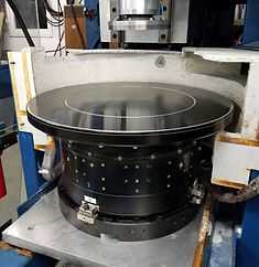
Large air bearing spindles are used on both the lapper and disc grinder machines to provide precision-flat platen surfaces and high rotational speeds.
The 19” diameter platens are flat to 0.0001” and rotate from 0 to 3,000 rpm.
The very stiff air-purged spindles repel abrasive debris and have spherical mount bases to provide perpendicular platen alignment with the lapper wafer head spindle.
Vacuum mounted abrasive discs protect the platen surface to continually maintain its required precision flatness.

Non-Precision-Flat Platens
Non-precision-flat platens can be used with the abrasive island discs. A island disc can be attached to a non-flat platen with vacuum and an abrasive disc attached to the workpiece (or wafer} holder and the islands ground flat into a common plane. The wafer abrading action will be totally smooth because all of the island surfaces are flat in the common plane that is perpendicular to the platen spindle axis of rotation.
After the disc islands are ground flat, both the disc and the platen are ink-marked at a common alignment location on the circumference of the platen. After the disc is marked, the disc can be removed and then re-attached to the platen at a later time where all of the island top surfaces will again be in a common plane. The re-mounted disc will provide smooth wafer abrading action. Multiple discs having different abrasive particle sizes can be ground flat to match the non-flat platen, alignment marked, and used interchangeably to progressively abrade wafers.
Vacuum mounted abrasive discs protect the platen surface to continually maintain its required precision flatness.
Multiple Wafers Polished
Multiple wafers can be abrasively polished simultaneously at high speeds by simply attaching them as a group to a flexible disc for vacuum mounting to the lapper wafer head.
Multiple Non-Equal Thickness Workpieces
Multiple-thickness wafers can be abraded together in groups that contact a flat planar abrasive island surface . With groups of non-equal thickness workpieces, the thickest wafers are abraded first, then the thinner wafers.
Double-Sided Wafer Abrading
Wafers are first attached to a wafer-disc and abraded. To abrade the opposing side of the wafers, they are simply flipped over, transfer-attached to a second wafer-disc and abraded.
Island Top-Surface Abrasive Conditioning Disc
If non-flat areas occur on the surface of a island abrasive disc, they can be easily and quickly removed with the use of a conditioning disc.
A standard flexible abrasive disc is attached to the lapper wafer head in place of the wafer disc.
Both the wafer head and the platen are rotated in abrading contact until the precision flatness of the platen abrasive disc is reestablished.
6” Sample Island Disc Abrade 2” Wafers, Test Set-Up #1


Keltech can supply to users a 6” disc having a 1.75” radial-width annular band of vitrified diamond agglomerate abrasive islands to abrade a 2” sapphire, SiC or GaN wafer at high abrading speeds.
Wafer abrade tests operated by you can provide both wafer cut-rate and island wear data using a very simple abrade test apparatus.
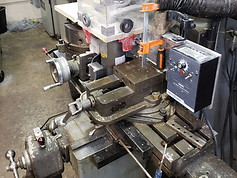
First, a 6” diameter, flat-surfaced disc hub is mounted on a variable speed DC motor that is attached to a standard shop milling machine. The 6” sample island disc is attached with adhesive to the disc hub.
Then, a 2” wafer is bonded to a 2” hub having a shaft that fits into the mill head. The wafer is then positioned in flat-surfaced contact with the disc islands where the 2” wafer is centered on the 1.75” wide band of islands on the 6” island disc. The 2” wafer overhangs both the inner and outer diameters of the annular abrasive band to provide uniform wear-down of both the wafer and the island discs.
A section of aluminum angle is attached to the mill head pivot arm and a steel weight bar is clamped to the aluminum angle. The arm weight applies a selected and constant downward abrade pressure force on the rotating wafer while in abrading contact with the rotating disc island abrasive. The wafer abrading pressure can be calibrated by sliding the weight along the arm angle while contacting a force weight scale positioned on the mill table while having force contact of the mill head wafer head with the scale.
Both the wafer mill head and the abrasive island disc are rotated at the same high speed (typically 1,000 rpm) and in the same rotation direction for a selected time ( typically 1 or 2 minutes) during the abrading test, using a cell phone timer attached to the mill.


6” Island Disc Abrade 2” Wafers, Test Set-Up #2


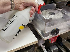
Coolant water is sprayed of the rotating island disc to cool the wafers by removing the heat generated by abrading friction. Water spray can be applied manually during an abrade test with the use of a water spray bottle or by a spray-control system.
For collecting wafer wear and island wear data for many independent abrade tests over a long period of disc and wafer abrade time, a fixed-position paint spray gun can be used. An air pressure regulator, a water jar and a water collection tray can be used to provide adjustable and uniform water coolant spray during all the series of tests.
For convenience, the wafer variable speed ½ hp dc motor and controller can be mounted to a 0.750” aluminum plate that is clamped in place by a standard milling machine vise attached to the mill X-Y table. The whole assembly can be easily removed and reinstalled with little alignments required. Also, positioning the wafer relative to the disc abrasive islands are easily and accurately replicated with use of the mill X-Y digital readout.
The wafer thickness can be accurately measured after each abrade test as the wafer hub is easily removed from the mill head. And, it is accurately repositioned in the mill head for the next abrade test. The wafer thickness is typically measured at 4 positions around the wafer circumference.
Measurements of the disc abrasive island heights are made less often as the disc island wear is so small. Six selected island thicknesses are typically measured at 6 ink-marked positions around the island disc circumference.
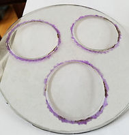
The front water guard is removable and held in place with magnets. Wastewater with sapphire debris is thrown radially off the rotating island disc. It impacts the water guard vertical walls and drips down the walls to enter the three angled folded-poly water troughs that progressively feed into each other. The water trough at the lower part of the back wall is used to direct all the water into a removable water collection tray.
The collected water typically has a milky-white color from the abraded sapphire debris.


Lapper: Air Pad Supported Platen
A precision-flat platen can be supported by air bearing pads distributed around the circumference of the platen to provide friction-free high-speed operation.
Use of a stiff, solid or sandwich platen having shallow vacuum grooves on the platen surface allows quick and strong attachment of flexible abrasive island discs and easy removal of abrading debris.
This simple design allows a robust and inexpensive lapper machine to be constructed. Air pads are positioned directly under multiple wafer heads to provide stiff support of wafers being abraded.
Low pressure air supplied by a blower to a controlled-leakage chamber at the platen bottom surface prevents contamination by abrasive debris.


Lapper: Tapered Roller Supported Platen
Multiple tapered rollers can be spaced around the periphery of a platen to provide rigid support to the platen as abrading forces are imposed on the platen by multiple wafer head abrading stations.
Each skid-free roller is tilted at an angle to have flat surfaced line-contact with the platen bottom surface. High-speed, precision roller bearings in each tapered roller allows the use of dimensionally stable, non-precision flat machine bases. Epoxy-sandwich brackets allow each roller assembly to be precisely aligned, in common, with the platen precision-flat bottom surface.
A sandwich-construction platen using top and bottom plates separated by a spacer provides a very stiff but low inertia platen that is easily accelerated and decelerated.
Shallow vacuum grooves in the platen top surface allows the quick and strong attachment of abrasive discs.


Vitrified Diamond Agglomerate Grinding Wheels
Vitrified diamond agglomerates can be coated or molded onto the surface of grinding wheel hubs to produce high quality and durable grinding wheels. Bonding the agglomerates with industry-standard solvent based phenolic adhesives provides a very simple method of wheel construction having a porous abrasive layer.
By comparison, the conventional system is to mold a mixture of glass powder and diamond particles on the wheel surface and placing the whole wheel in a furnace to melt the glass during vitrification to bond the individual diamond particles to the wheel. Special materials added to the glass mixture form gasses at high temperatures that create the required void spaces within the abrasive layer.
Using diamond abrasive agglomerates that have been independently pre-vitrified in a furnace allows the grinding wheels to be produced at room temperatures and fully cured in an oven. Evaporation of the solvent from the adhesives during curing produces the void spaces in the abrasive layer used for improved workpiece cut rates and cooling by the porous wheel.


Vitrified Diamond Agglomerate Non-Island Abrasive Discs
Vitrified diamond agglomerates can be coated with adhesives on the surface of polymer discs or on continuous webs. Abrasive sheets, strips or discs can be cut from the webs.
Pre-vitrified diamond abrasive agglomerates are simply coated on the polymer backing discs (or webs) using conventional coating processes and solvent-based adhesives. Evaporation of solvent from the adhesives during curing produces the void spaces between individual agglomerates that provide high cut rates of hard materials and effective cooling of workpieces.
The agglomerates provide long disc abrade life and support individual expensive diamond particles as they slowly wear down and continually resharpen before they are ejected and replaced with new sharp particles.
A wide range of abrasive particle sizes and abrasive materials can be encapsulated by the solidified glass during vitrification.

